PHYS 2426 – Engineering Physics II
Coulomb’s Law
Leader: _________________________ Recorder: __________________________
Skeptic: _________________________ Encourager: ________________________
Materials
Coulomb Balance Apparatus (
Kilovolt Power Supply (
Laptop (for graphs)
Figure 1 Typical Setup
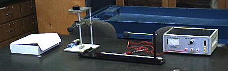
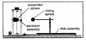
Figure 2 Block Diagram View
Introduction
In
this experiment we will investigate the factors that affect the electrostatic
force between two charged spherical conductors.
Our apparatus will consist of a torsional pendulum and a high voltage
power supply as shown in figure 1. We
will use the power supply to place the same charge on two spherical conductors
and vary the distance between them. As
we bring the spheres near each other we will observe a force between them and we
will measure a quantity proportional to the force, namely the angle through which
the torsional pendulum turns. From the
measured angle, we will be able to determine the force. The relationship between the force and the
angle in degrees through which the torsional pendulum turns is given by the
equation ![]() where
where ![]() (1). The value of Ktor varies slightly for each Coulomb Balance Apparatus but
the difference has been found experimentally to be small. It is also time consuming and tedious to
measure the value of Ktor, so to find the force that produces a
given deflection we will use equation (1).
(1). The value of Ktor varies slightly for each Coulomb Balance Apparatus but
the difference has been found experimentally to be small. It is also time consuming and tedious to
measure the value of Ktor, so to find the force that produces a
given deflection we will use equation (1).
Procedure
1. Setup
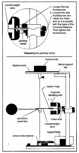
The Coulomb balance apparatus should already be set-up but you first need to verify that the sliding sphere is set in the correct position so that accurate distance data is obtained. If not already done so, loosen the clamp holding the pendulum assembly – see figure 3. Move the sliding sphere indicated in figure 2 so that it is positioned at the 3.8 cm mark. At this point the spheres should just touch since this is the distance between the centers of the spheres. If the spheres miss or displace each other, notify your instructor.
Gently touch both of the spheres to remove any charge. If not already done, turn the torsion knob so that the degree scale reads 0˚. Zero the torsional pendulum by rotating the plastic piece holding the wire on the bottom of the apparatus until the line on the counter balance pan aligns with the index mark. Move the sliding sphere – see figure 2 - to its maximum separation from the suspended sphere.
Setup of the Balance
2. Set up the high voltage power supply
Make sure that the high voltage (HV) power supply switch is in the off position, and that the adjustment knob is turned fully counter clockwise. The charging probe should be plugged into the plug labeled 6 kV on the front of the power supply. Make sure that the HV power supply is plugged in.
3. Qualitative Observations
Make sure that the sphere on the slide is at the maximum distance from the other sphere. Turn on the power supply and rotate and adjust the voltage so that it reads 6 kV. Touch each of the spheres successively for several seconds with the probe. Remove the tip, turn down the voltage and turn off the power supply. Rapidly but gently move the sliding sphere so that it is close to the other sphere but not touching. Continue pushing the two spheres closer together.
Q1) Describe what you see.
Q2) Is the force attractive or repulsive in this case? What does that mean about the charges on the spheres?
Separate the spheres again. Gently touch them to remove any charge. Turn on the power supply and rotate and adjust the voltage so that it reads 6 kV. This time touch only the sphere on the slide for several seconds with the probe. Remove the tip, turn down the voltage and turn off the power supply. Gently but quickly slide the spheres together so that they are close but not touching.
Q3) Describe what you see?
Q4) You should have observed at first the spheres attracted. Use the fact that the spheres are coated with graphite which is a conductor to explain why at first the spheres attracted. Draw a picture illustrating your explanation.
Q5) Once the spheres touched you should have observed that they then repelled. Explain why. Draw a picture illustrating your explanation.
Gently touch each of the spheres to remove the charge from them and separate them to maximum separation.
4. Determination of Dependence of Force on Distance
In this part of the lab we will now investigate some of the features of the electrostatic force quantitatively. You need to perform each trial (in italics) rapidly but carefully so that you obtain good data.
Turn on the power supply and rotate and
adjust the voltage so that it reads 6 kV.
Touch each of the spheres successively for several seconds with the
probe. Remove the tip, turn down the
voltage and turn off the power supply.
Rapidly but gently move the sliding sphere so that it is at the 20 cm
mark. Measure the torsion angle by
turning the knob so that the pan returns to the equilibrium position. Record the distance and the torsion angle in
the data table below. In all parts of the lab, make sure that the apparatus is
properly zeroed before each trial.
|
Distance (cm) |
Torsion Angle (°) |
Force (N) |
|
|
|
|
|
|
|
|
|
|
|
|
|
|
|
|
|
|
|
|
|
|
|
|
|
|
|
|
|
|
|
|
Discharge the spheres, and return them to maximum separation. Repeat the procedure for separations of 14, 10, 9, 8, 7, 6, and 5 cm respectively.
Q6) Did the force become stronger or weaker as
you moved the spheres together?
Q7) Does this suggest that there is a direct or inverse relationship between the force and the distance? Explain.
Use equation (1) to calculate the force for each trial and fill it in the data table.
Open LoggerPro. Click OK to proceed without the interface. You should have a data table in which you can enter your force and distance data to construct a properly labeled graph of Force vs. Distance. (Remember when we say Force vs. Distance, Force is the vertical axis and Distance is on the horizontal axis.) Attach the graph to the report.
Q8) Does your graph appear to agree with your answer to Q7)? Explain.
We expect some sort of inverse relationship. To find the power, click on the curve fit
button ![]() . Choose a Power fit, click on Try Fit, and
then accept the fit.
. Choose a Power fit, click on Try Fit, and
then accept the fit.
Q9) Record the power given by the fit.
Q10) Is the exponent you obtained close to -2? (It will very unlikely be exactly -2)
An exponent of -2 would mean that there is an inverse square law between the force and the distance.
5. Determination of Dependence of Force on Charge
We are assuming that the charge on the spheres is proportional to the voltage applied to them. We can then change the charge by changing the charging potential. We will now investigate how the force depends on the charge on each of the spheres.
Separate the spheres to their maximum separation, turn on the power supply and turn up the potential to 6 kV. Apply the touch wand to each of the spheres for several seconds, then turn down the potential and turn off the power supply. Smoothly but rapidly bring the spheres to a separation of 5.0 cm. Measure the angle of deflection of the pendulum as before and record in the data table below.
Now, repeat the procedure by charging the suspended sphere with 6 kV, but turn down the potential to 5.5 kV and then charge the sliding sphere. After charging both spheres rapidly but smoothly move them to a separation distance of 5.0 cm and record the deflection angle as before.
Repeat the procedure 3 more times each time charging the suspended sphere with 6 kV, but charging the sliding sphere with 5.0 kV, 4.5 kV, and 4.0 kV, respectively. Each time measure the deflection angle at a separation distance of 5.0 cm.
|
Potential Applied to Sliding Sphere (kV) |
Potential Applied to Suspended Sphere (kV) |
Deflection Angle (°) |
Force (N) |
|
|
|
|
|
|
|
|
|
|
|
|
|
|
|
|
|
|
|
|
|
|
|
|
|
Use equation (1) to determine the force for each trial.
Q11) How does the strength of the force change as you decreased the charging potential applied to the sliding sphere?
Q12) What does this suggest about the relationship between the charge on the sliding sphere and the force?
Q13) Construct a properly labeled graph of Force vs. Charging Potential. Assuming that the charging potential is proportional to the charge on the sphere, how does the force between the spheres depend on the charge on the sliding sphere? Attach the graph to the report.
Q14) In the case where we charge each potential we assume that we have the same charge on each. Use the data from that trial and Coulomb’s law to determine the charge on the sphere. Be careful about units.
Q15) Identify any likely sources of error in this experiment. Do not use meaningless catchalls like “experimental error, “measurement error”, or “human error”. Be specific. Think carefully about how the experiment was conducted and what factors and assumptions might not have worked perfectly.