Note to students:
In the article the example engine is an air-cooled Corvair engine for an aircraft application. It is unlikey you will see too many of these, but the principles and practices explained here can apply to the engines you do work on.
The heads and case that came with my "Wisconsin" engine were
pretty corroded on the outside (thanks to salty roads), so I bought another
engine from a guy in
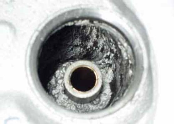
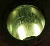
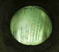
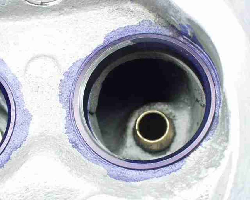
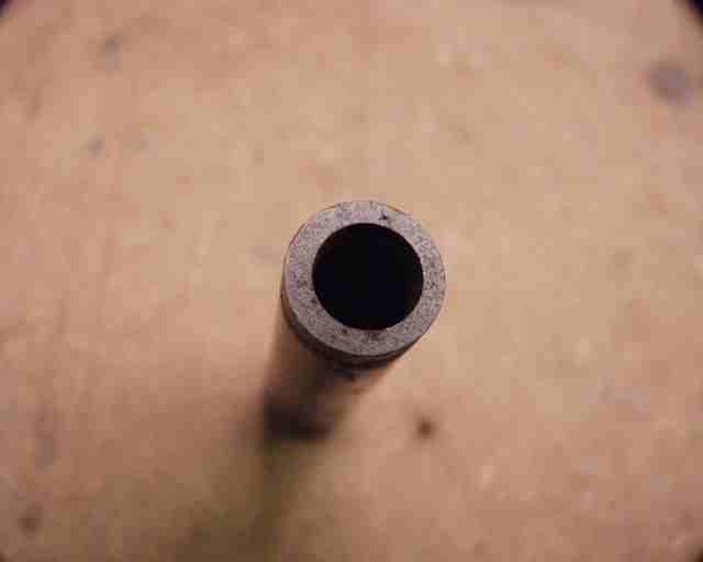
Get a look at this valve port corrosion that I found underneath! This is from
water sitting behind the valve for DECADES until somebody decided to do the
valve job on it! And ALL of the ports looked that way! So it turns out my
externally corroded engine is in far better shape than the clean one with the
heads freshly "rebuilt". It's this kind of stuff that makes me glad
I'm skeptical! The guides had been reamed out to the next size and oversize
valves installed, but the ports were so corroded I could never trust them not
to loose a chunk of aluminum, not to mention flow problems, so these are junk.
I wasn't real impressed with the quality of the "valve job" either.
The stem/guide clearance was actually way too tight as well. So I used the
"externally" corroded heads, which cleaned up very nicely with a
little walnut hull blasting work.
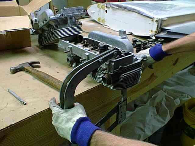
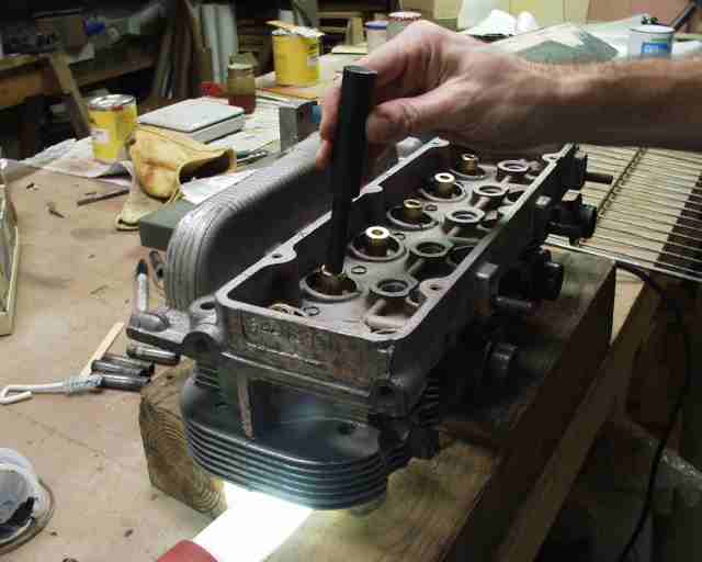
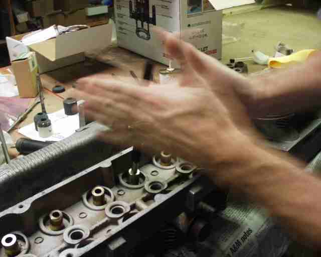
A large C-type valve spring compressor can be used to remove the valves and springs.
A good whack on the top of the compressor when you get close to compressing it
all the way will help break the keepers loose. No, I don't normally use a claw
hammer to work on engines, but my wife was using the ballpein.
What a woman!
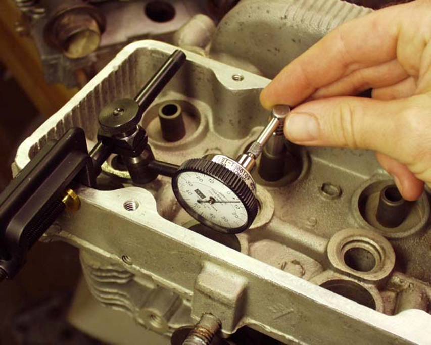
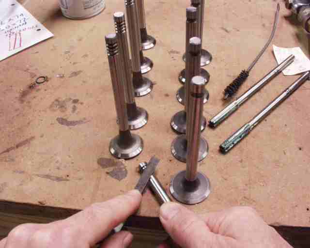
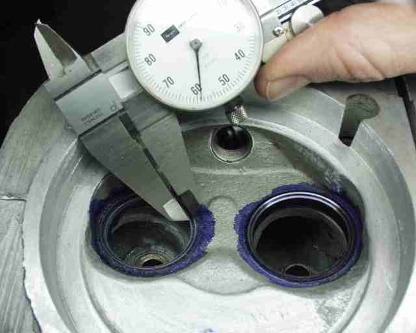
Here's the setup for measuring valve guide play. The spec is
.001"-.0027" for intakes, .0014"-.0029" for exhausts,
according to GM's manual. Up to .005" is OK for "used" guides,
but since all of mine are more than .005", out they come. This is not
something that you want to do "just to be thorough". If your guides
are not out of spec, don't mess with 'em! For
aircraft use, we want to be on the high side of the tolerance anyway, due to
the long duration of high heat usage. And there's the matter of valve guide
concentricity that we'll talk about in a minute.
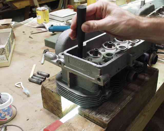
Removing guides is done with the official tool from
If you have been living "right", this is what your valve guide bores
will look like.
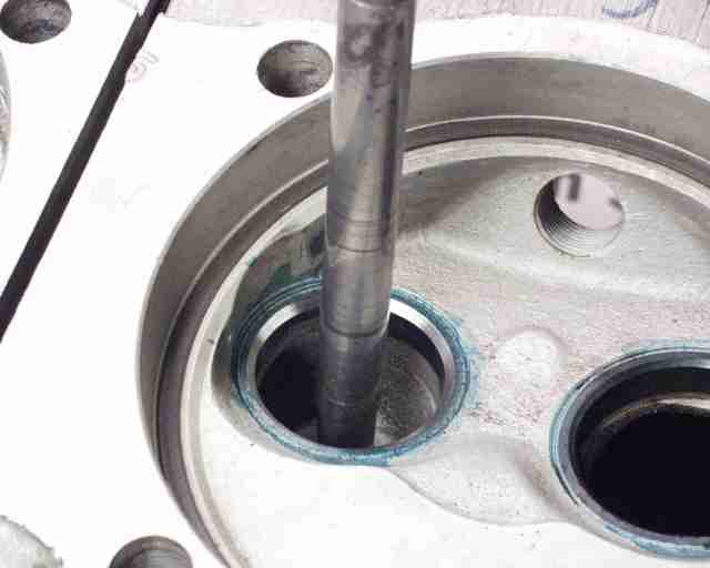
If you haven't, you might get one like this, which shows some galling as the
guide was driven out. I worried about the fit of the new guide, but it was just
as hard to drive in as the rest, so I'm convinced that it's just fine.
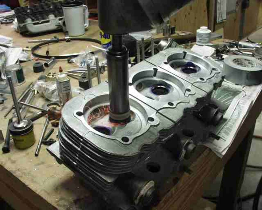
Installation is reverse, again by heating the head to 475 degrees, but they
come in from the spring side, and the guides should come directly from the
freezer and be lubricated with grease. That's the black stuff that you'll see
around the guides throughout the rest of this page. Also, I marked each bore
with an I or an X to show me where the intakes would
go and where the exhausts belonged. When that head is cooling (and too hot to
handle!) you don't have time to be wondering which one goes where. And I
wouldn't have wanted to drive one of these back OUT again!
I chose to use the racing quality Otto valve guides, which are beefier on
the top end and tapered for better flow on the intakes. Regular ones are just
fine, but I like to build in all the reliability and performance that I can,
since I'm going to this much trouble anyway. One other difference is that Otto
guides have no provision for mounting valve guide seals, which aren't necessary
or desired as long as your stem/guide clearance is up to spec.
Initial reaming is done with a hand drill and a .3420" reamer, working up
to my eventual .3435", on .0005" increments. My valve stems were
.3415", so that's .002" of clearance, right in the middle of the
"new" range.
Before you put any of your new valves into your freshly reamed guides, make
sure that there are no burrs on any of the valves' keeper grooves. I used a
worn out "point" file for that job, but didn't find anything to worry
about.
After reaming to the smallest diameter that you think you'll need, clean out
the bore and insert a valve and check it's stem to valve clearance (like I did
originally to determine if I needed new guides). Mark this valve so that it
always goes back in the same guide. Tolerances on new valves are pretty close,
but they are still not identical. You can use this to your advantage by
swapping them around until you get a perfect fit. All of my intakes were
slightly larger than my exhaust valves, which I think is a deliberate attempt
to give larger clearances on the exhausts, since they run much hotter than the
intakes.
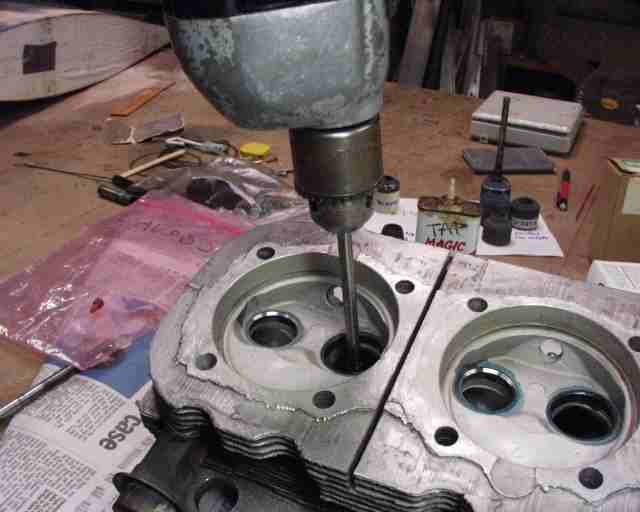
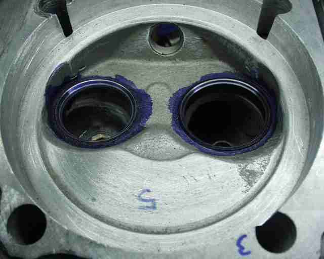
An 11/32" pilot shaft is inserted into the valve guide for a grinding
stone holder to ride on. The blue stuff is Dykem
machining dye, which makes it easier to see what you're doing. This seat has
already had the seat cut. Astute readers will notice that this head's not been
bored yet. That's because this picture was made when I was doing Mark Jones'
valve job. I should have made a "before and after" shot, showing the
little pits of seat erosion that would have eventually promoted
"burning" a valve face.
The grinding stone is spun by a special right angle drill made for the job.
Here you can see the sparks flying as the seat is reground. Let the record show
that this is definitely "old school" valve grinding equipment, bought
cheap at a "real" garage sale, where the mechanic was retiring and
closing up shop. This works fine, but is more work than the new method, the
"Neway Valve Seat Cutter". See more on that
at the update down at the bottom of this page.
Sometimes you'll discover that your guide is not concentric with the valve
seat. See how only the left half has been resurfaced, but the right side is
untouched? Don't worry, it's nothing that you did
wrong...
...it's something GM did wrong! At the time, I didn't know how GM managed to
make a valve guide as screwed up as this one is, but I found about four of them
in my head that any bozo could see were not drilled coaxial to the outer
surface. But after a little extra grinding, all is well with the seat but now
your valve sits lower in the head and this chamber now has more volume than the
rest. Somebody later told me that GM drilled the guides out at the same time
they faced the valve seats, so I guess that explains the lack of concentricity
with the guides. It makes replacing the valve guides more of a chore though.
Now that the seat is refaced, you need to return it to the proper width,
along with all the others.
After the seat is refaced, it's painted with dye again, and narrowed to the
specs (.030"-.050" for intakes, .060"-.070" for exhausts,
according to Fisher's "How to Hotrod Corvair
Engines) using 60 degree and 30 degree stones. It is also best to raise the
contact area on the intakes so it's on the outer 1/3" of the valve face,
while the exhaust face's contact area should be centered. This is what's known
as a "three angle" valve job, and costs extra at the machine shop. If
you didn't ask for it, you didn't get it. And you might not have gotten it even
if you DID ask for it. You could argue that any flow work done won't contribute
much at the low RPMs that we run at, but I can do it,
so I am. But I'll be the first to admit that most CorvAircrafters
would be wasting their money to go to this extreme.
Also notice in this picture how all sharp edges of the combution
chamber have been removed with a dremel tool or die
grinder and then sanded smooth with sandpaper. This helps prevent pre-ignition
from originating at the red hot glowing sharp edges, which is very important to
avoid in an engine that's going to run most of it's
life near full power. Later I'll polish the whole thing to reflect heat back
into the chamber and to minimize carbon buildup. I've also used the die grinder
to clean up all the gross casting flaws in the ports, and radius the ports in
places where it's obviously needed. I also used 600 grit
sandpaper to round the edges of the valve seat cuts to improve flow there.
But unlike the three angle valve job, anybody can and should round off the
sharp edges in the chamber to prevent pre-ignition. A couple of sheets of sand
paper is all you need. Also note just below the right
valve there's a little area of casting that wasn't quite removed when the head
was bored for the cylinders at the factory.
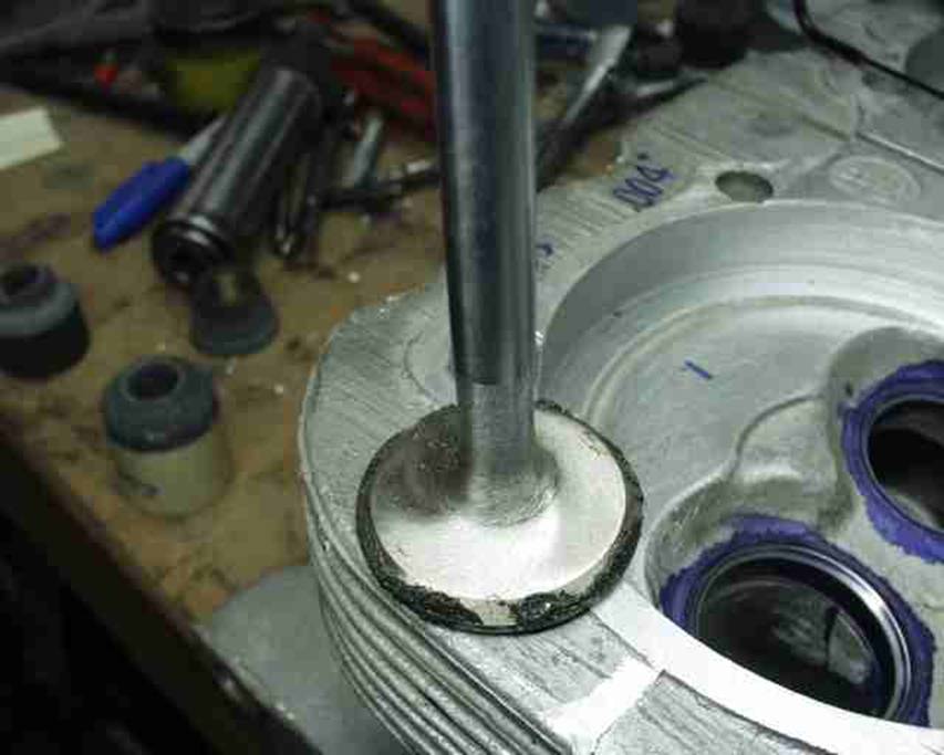
The valve facing work is to "lap" the valves using valve grinding
paste. A little of this abrasive concoction is spread on the valve seat and
then...
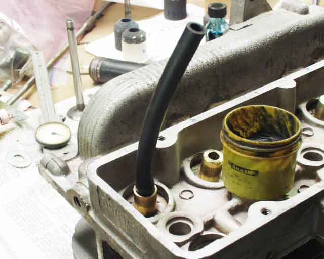
a short length of rubber hose attached and then...
pulled upward and rotated to "lap" the valve
to the seat, making a perfect seal.
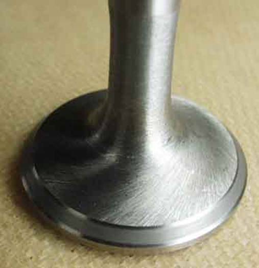
The resulting indication of where the valve seals is
clearly visible on a new valve, but Prussian blue dye (Dykem)
is helpful if the valves are used or previously lapped. Check to ensure that
the contact area is the proper width and stays that way all around the face,
although it almost HAS to at this point! If it's not, it's because your valve
is bent! It looks like this one can stand a little seat narrowing still, but
the contact area is centered, as it should be for an exhaust valve.
These valves are Corvair Underground's stainless
steel swirl polished valves, with chromed stems and stellite
faces. They are only slightly more expensive that the other stainless valves,
at around $10 each.
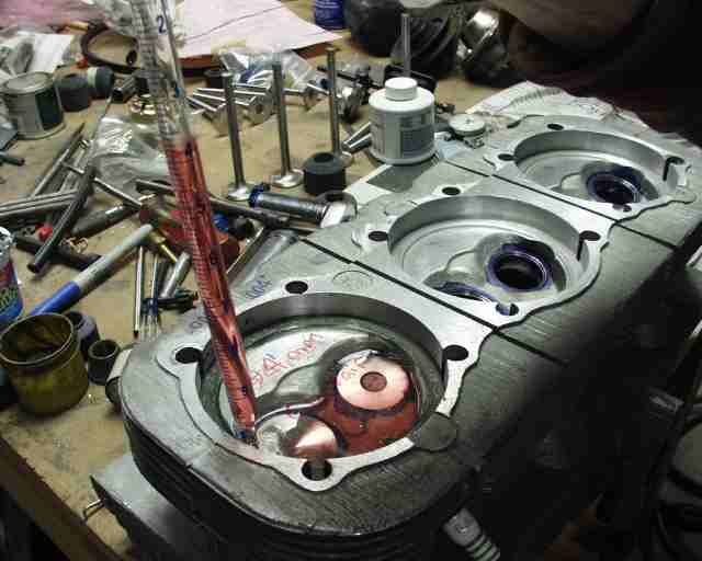
Next you need to "cc" the combustion chambers so that you can set up
your desired compression ratio. First install a sparkplug and torque it to
specification. This is a good time to find out if you need to Timesert a plug hole, rather than AFTER the engine is
assembled. Then install the two valves with a thin coat of grease on the faces
to prevent leakage. Next I cut a disk out of 1/8" plexiglass,
and drilled two holes in it, one the size of my pipette and the other for an
air escape hole. A thin film of grease is smeared around the edges to seal the
chamber, and the plate is inserted into the chamber and rotated a little to
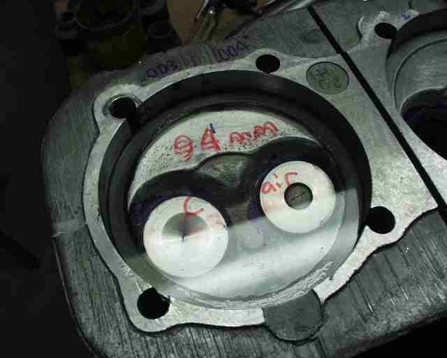
seal the grease. Level the head with a torpedo level across the machined fin
surface. I wrote "94mm Corvair" on it to
identify it from one of several others I've cut over the years, mostly for VW
work.
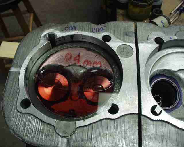
I used kerosene for this, since it flows easily and is visibly red. Some people
use ATF but it's far more prone to having bubbles get stuck under the plexiglas and mess up your
readings. I sucked the kerosene up into the 10cc pipette and quickly held my
finger over the top end and gradually released pressure to drop the level to
where the miniscus (the lower edge of the U shaped
top surface of the column) read exactly 10cc (or ml, same thing), making sure
that I was viewing the pipette directly from the side, while the end was still
submerged in fluid. Then I transfered the pipette
over to the plexiglas disk
and released my finger to empty the contents into the chamber.
Do this four times, watching the bubble of air and making absolutely sure that
the fluid doesn't escape out one of the holes, just the air. This is where
previously leveling the head comes in handy. I also keep a wooden
"builder's shim" (for shimming doors and windows) under one edge of
the head for minor corrections to keep the bubble headed up toward the air
escape hole. Be careful not to get carried away though, because when you remove
the pipette to reload it it might come out THAT hole,
so you want it just slightly out of level biased toward the air escape hole.
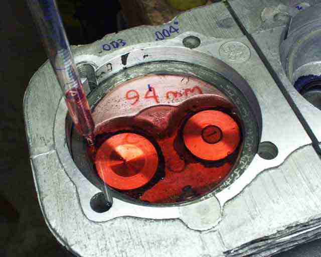
When the air bubble disappeared completely, I had released 48.3 cc's into the
chamber. The second one was 48.7 ccs and the third
one (number 5) is 49.1. That's in line with my theory that GM didn't bore this
head the same depth on all three cylinders. Maybe the valve cover surface isn't
in the proper plane assuming that's the flat surface they use when milling the
chambers for the cylinder bores. The other head is 47.5,47.8,
and 47.8. Now all I have to do is find the largest one, and remove a little aluminum
from the five smaller ones so that they all match within .1cc.
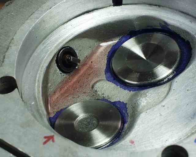
I wanted to get an idea of how much 1cc of volume looks like, and this is a
picture of it. Right now I have a spread of 1.6 ccs,
so I have some work to do. I may only do one more iteration,
but the result will be combustion chambers of similar volume, which will give
me similar power from all six cylinders. And more importantly, I will KNOW what
my compression ratio is, rather than guessing. This is part of the
"blueprinting" process of eliminating manufacturing tolerance stackup. You might have noticed that my cylinder number 5
(about 10 pictures ago) either wasn't machined to the same depth (by the
factory) or the casting wasn't quite as tall, so there is a definite need to
see which is the case.
But if for no other reason, you need to cc at least ONE chamber (the middle one) from each head so that you can average them and calculate your compression ratio and adjust it with shims to whatever your desired CR is. I'll make mine 9.25, just like the stocker,which is rumored to have actually been closer to 8.25 by Fisher, despite the factory claim. [Mine eventually ended up at 9.02:1, which is fine with me]. Even the GM specs listed on my web page list the CR as being in the 8.7:1 range. Keep in mind that even IF the factory CR claim was correct, boring out to a larger diameter piston automatically raises the CR somewhat.